Home
/ 555 Timer Ic Schematic Diagram : Astable Multivibrator Utilizing 555 Timer Circuit Obligation Cycle Purposes Electrician World News, Its name is derived from three 5k ohm resistors ,connected in series used in it.the timer ic can produce required waveform accurately.
555 Timer Ic Schematic Diagram : Astable Multivibrator Utilizing 555 Timer Circuit Obligation Cycle Purposes Electrician World News, Its name is derived from three 5k ohm resistors ,connected in series used in it.the timer ic can produce required waveform accurately.
555 Timer Ic Schematic Diagram : Astable Multivibrator Utilizing 555 Timer Circuit Obligation Cycle Purposes Electrician World News, Its name is derived from three 5k ohm resistors ,connected in series used in it.the timer ic can produce required waveform accurately.. Figure 2 shows the basic 555 timer monostable circuit. As discussed in the above section, the ic is in its standard monostable mode. 555 ic timer block diagram 555 ic timer block diagram. Resistive network consists of three equal resistors and acts as a voltage divider. Suitable for various test circuits.
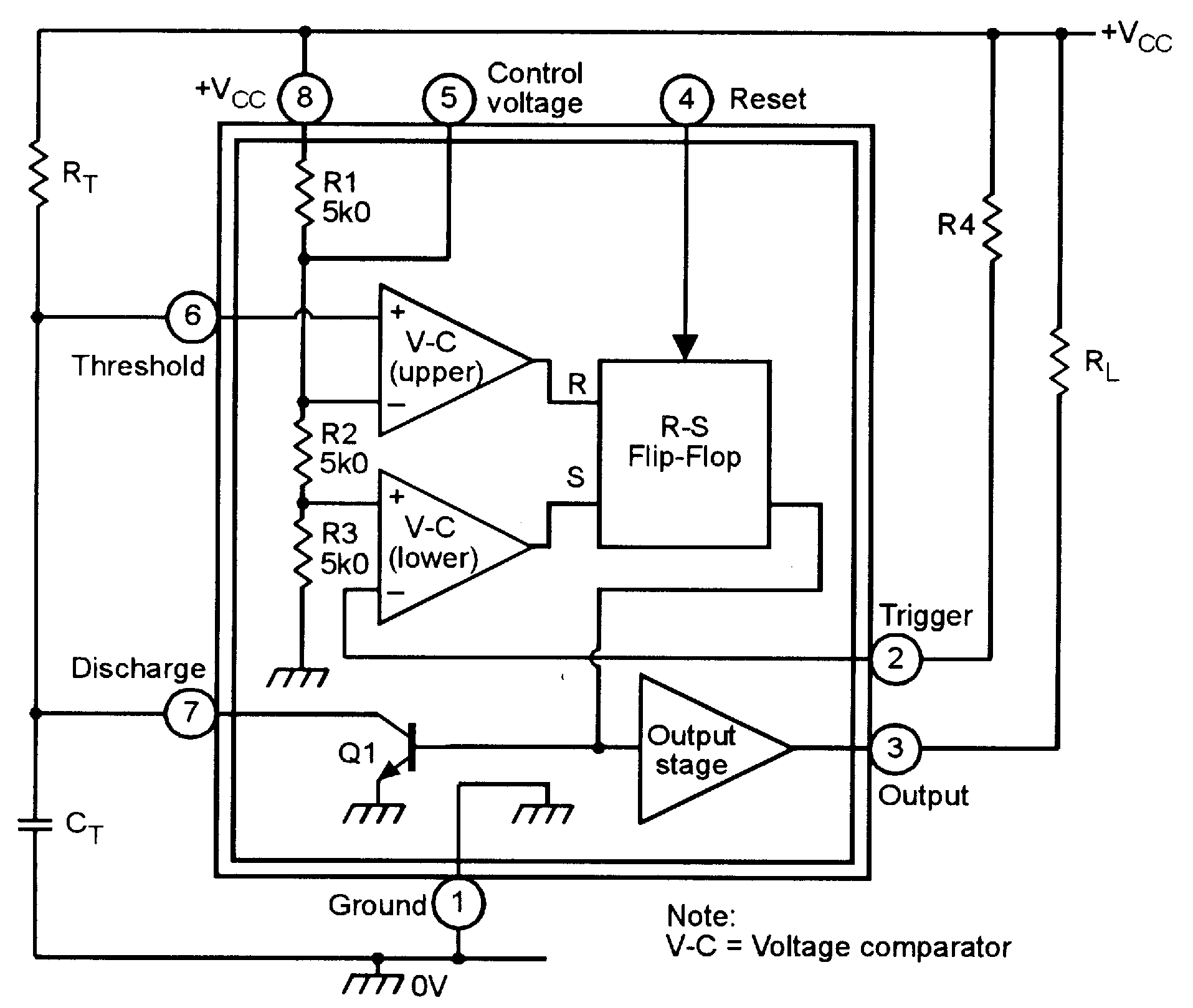
The 555 timer ic is an integral part of electronics projects. Figure 1 is the pinout and functional block diagram for the 555 timer ic. Derivatives provide two or four timing circuits in one package.it was commercialized in 1972 by signetics. 555 ic timer block diagram 555 ic timer block diagram. Although the schematic looks correct, this basic circuit may actually have a few negative aspects.
555 Monostable Circuits Nuts Volts Magazine from www.nutsvolts.com In this category, we have handpicked some really useful 555 timer circuits which will be interesting to electronics engineering students and hobbyists alike. Now as shown in figure, there are eight pins for a 555 timer ic namely, 1.ground. In the place of the push switch s1 / trigger switch you can also connect the output of any project to trigger the timer. It is connected to ground as usual. Pin diagram of 555 ic. Two tone generator circuit using 555. Resistive network consists of three equal resistors and acts as a voltage divider. Daman shah june 5, 2021.
The working modes of a 555 timer are astable, bistable, and monostable.
How much voltage and current will come. 555 timer pin diagram and descriptions. Although the schematic looks correct, this basic circuit may actually have a few negative aspects. 555 timer is an industrial standard ic existing from early days of ic. The circuit diagram to operate the 555 ic in astable mode is shown be 555 timer, as the name specified, are the electronics circuits used for measuring time intervals.in this article, we will cover about 555 timers. Simple 555 timer circuits & projects. The circuit will not repeat it's timing cycle if the push switch s1 will remain on or pressed, after a timing cycle is completed. 555 datasheet 555 duty cycle 555 metronome 555 reset function 555 time delay relay inverted 555 timer pulse generator. When a 555 timer is operating in astable mode we obtain a pulse on the output pin whose on time (time high) and off time (time low) can be controlled. The 555 timer ic is a very cheap, popular and useful precision timing device which can act as either a simple timer to generate single pulses or long time delays, or as a relaxation oscillator producing a string of stabilised waveforms of varying duty cycles from 50 to 100%. Daman shah june 5, 2021. Derivatives provide two or four timing circuits in one package.it was commercialized in 1972 by signetics.
This is a simple noise generator circuit. Internal circuit diagram of 555 ic. We have a large collection of simple and advanced projects using 555 timer ic. There are simple circuits for beginners and advanced engineers. These on off intervals can be adjusted by varying the 555 timer output and number of counter outputs.
Adjustable Timer Circuit Using 555 from theorycircuit.com Each mode of operation indicates a circuit diagram and its output. Working modes of 555 timer ic. Once this switch is pushed, the circuit pulls its output to a. Here you have separate on and off buttons to control an led. The 555 timer ic is an integrated circuit (chip) used in a variety of timer, delay, pulse generation, and oscillator applications. How much voltage and current will come. Various light actuator and relay driver circuits are also further enclosed. Referring to the timing diagram in figure 3, a low voltage pulse applied to the trigger input (pin 2) causes the output voltage at pin 3 to go from low to high.
Figure 2 shows the basic 555 timer monostable circuit.
This integrated circuit can be used in a variety of ways from which the basic one is to produce accurate and stable delays in electronic circuits.additionally, it is available in 8 pin dip and 14 pin dip. The working modes of a 555 timer are astable, bistable, and monostable. This controlling can be done by selecting the appropriate values for the resistor r1,r2 and capacitor c1. Operation of the circuit is when the power supply to the circuit. Note this ckt diagram runs or burnt this type. We have a large collection of simple and advanced projects using 555 timer ic. The following schematic shows two additions to the basic 555 timer circuit. Figure 1 is the pinout and functional block diagram for the 555 timer ic. Now, you can easily design the different timer circuits of 1minute,5 minute,10 minute and 15 minute using 555 timer ic with ease. Adjustable on off timer(using 555 astable mode) in this circuit a timer with cyclic on off operations is designed. The 4rth circuit diagram shows the standard ic 555 adjustable timer circuit having two sets of timing ranges and an output relay for toggling the desired load. Basic 555 monostable multivibrator circuit. The 555 timer ic is an integrated circuit (chip) used in a variety of timer, delay, pulse generation, and oscillator applications.
Note this ckt diagram runs or burnt this type. The working modes of a 555 timer are astable, bistable, and monostable. The 555 timer ic is an integral part of electronics projects. As we know 555 timer ic is one of the commonly used ic among students and hobbyists. The 4rth circuit diagram shows the standard ic 555 adjustable timer circuit having two sets of timing ranges and an output relay for toggling the desired load.
555 Timer Delay Off Circuit Diagram from www.eeweb.com The values of r1 and c1 determine how long the output will remain high. The standard 555 timer ic is made of 2 diodes. 555 timer is an industrial standard ic existing from early days of ic. Referring to the timing diagram in figure 3, a low voltage pulse applied to the trigger input (pin 2) causes the output voltage at pin 3 to go from low to high. The circuit will not repeat it's timing cycle if the push switch s1 will remain on or pressed, after a timing cycle is completed. From our earlier discussions we know that for a 555 in the delay timer mode, the delay could be accurately managed through a single external resistor and one capacitor. Operation of the circuit is when the power supply to the circuit. There are simple circuits for beginners and advanced engineers.
We have seen in the last few tutorials that the 555 timer can be configured with externally connected components as multivibrators, oscillators and timers, with timing intervals ranging from a few microseconds to many hours.
Monostable 555 timer circuits will automatically trigger and start a timing cycle when power is applied to the circuit. Each mode of operation indicates a circuit diagram and its output. Now as shown in figure, there are eight pins for a 555 timer ic namely, 1.ground. Resistive network consists of three equal resistors and acts as a voltage divider. 555 timer, as the name specified, are the electronics circuits used for measuring time intervals.in this article, we will cover about 555 timers. Two tone generator circuit using 555. As discussed in the above section, the ic is in its standard monostable mode. Referring to the timing diagram in figure 3, a low voltage pulse applied to the trigger input (pin 2) causes the output voltage at pin 3 to go from low to high. Let us discuss in detail about this circuit. As we know 555 timer ic is one of the commonly used ic among students and hobbyists. There is also a 556 dual version of 555 timer which consists of two complete 555 timers in 14 dip and a 558 quadruple timer which is consisting of four 555 timer in one ic and is available as a 16 pin dip in the market. The 4rth circuit diagram shows the standard ic 555 adjustable timer circuit having two sets of timing ranges and an output relay for toggling the desired load. The timer's internal circuitry is largely responsible for this triggering but it is also caused stray or installed capacitance at the trigger input of the timer.
We have seen in the last few tutorials that the 555 timer can be configured with externally connected components as multivibrators, oscillators and timers, with timing intervals ranging from a few microseconds to many hours 555 timer schematic. The timer's internal circuitry is largely responsible for this triggering but it is also caused stray or installed capacitance at the trigger input of the timer.